
P&P-DCD
Precise die-cut dispensing for stable, flexible, and easy-to-integrate automation processes.
What Is the P&P-DCD?
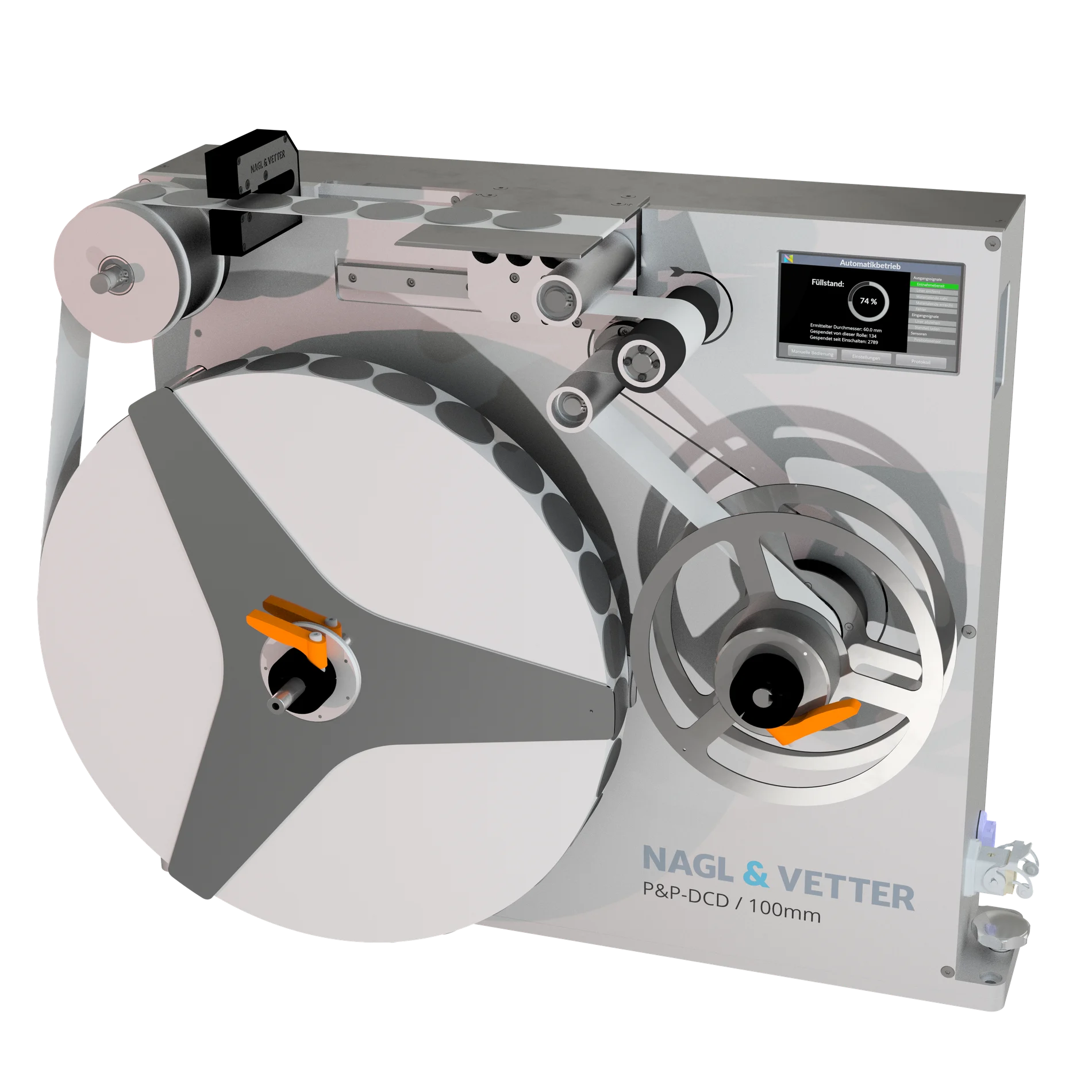
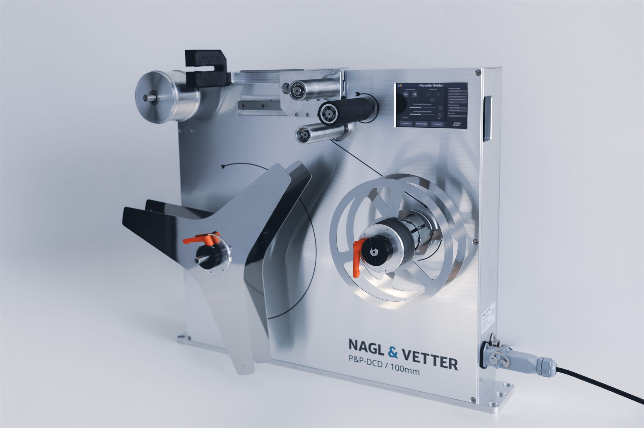
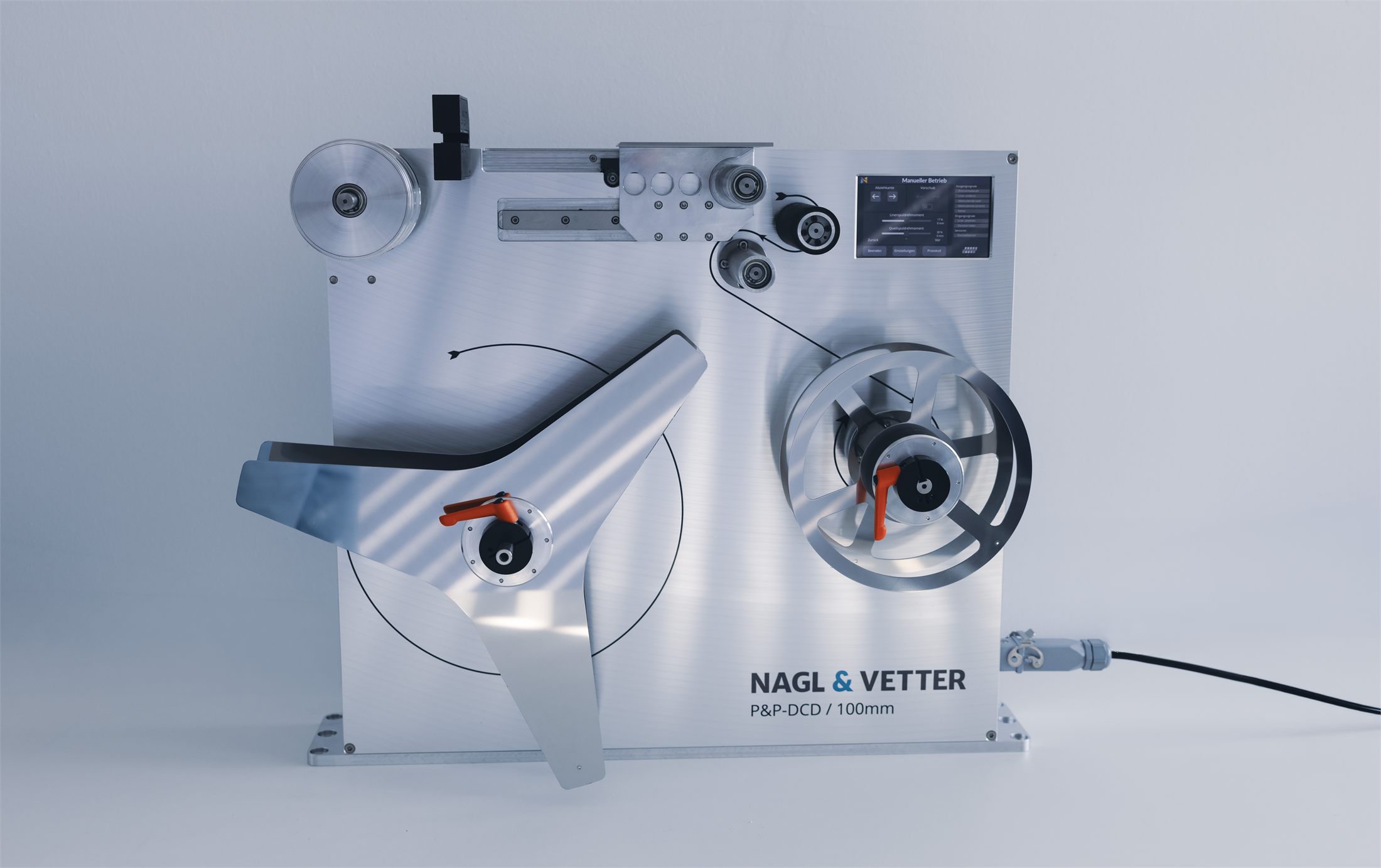
The P&P-DCD detects die-cuts on the roll liner and positions them at a defined pick point. Picking itself is done by the gripper on the machine side, not by the DCD. After the pick, the DCD automatically retracts the liner.
- Self-contained unit with no external control cabinet or pneumatics required
- Positions parts precisely at a defined pick point for the machine-side gripper
- Automatic liner retraction after each pick
- Multi-dispenser mode: up to 4 die-cut pads in parallel
TAPE BREAK DETECTIONProcess monitoringFLEXIBLE
DIE-CUT LOADING
Why Pick & Place Instead of Direct Application?
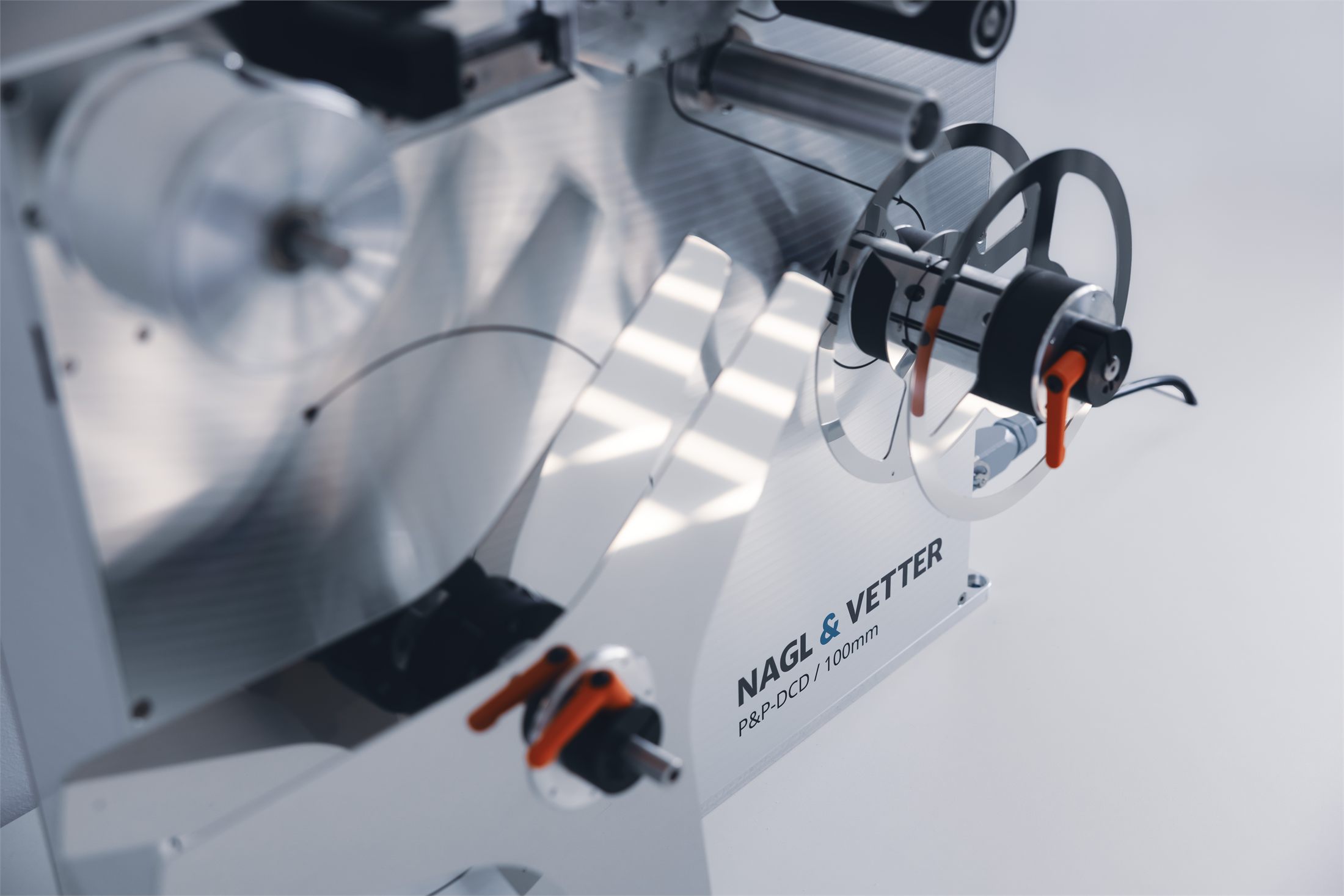
When the set point, part geometry, or cell layout rule out direct application, the P&P-DCD offers a pick-and-place path within the Nagl & Vetter portfolio, complementing the i-DCA rather than replacing it.
- An alternative when direct robot-mounted application isn't feasible.
- Works with your existing pick-and-place gripper or robot cell.
- Fits process and accessibility requirements the i-DCA cannot address.
How Is the Dispensing Process Monitored?
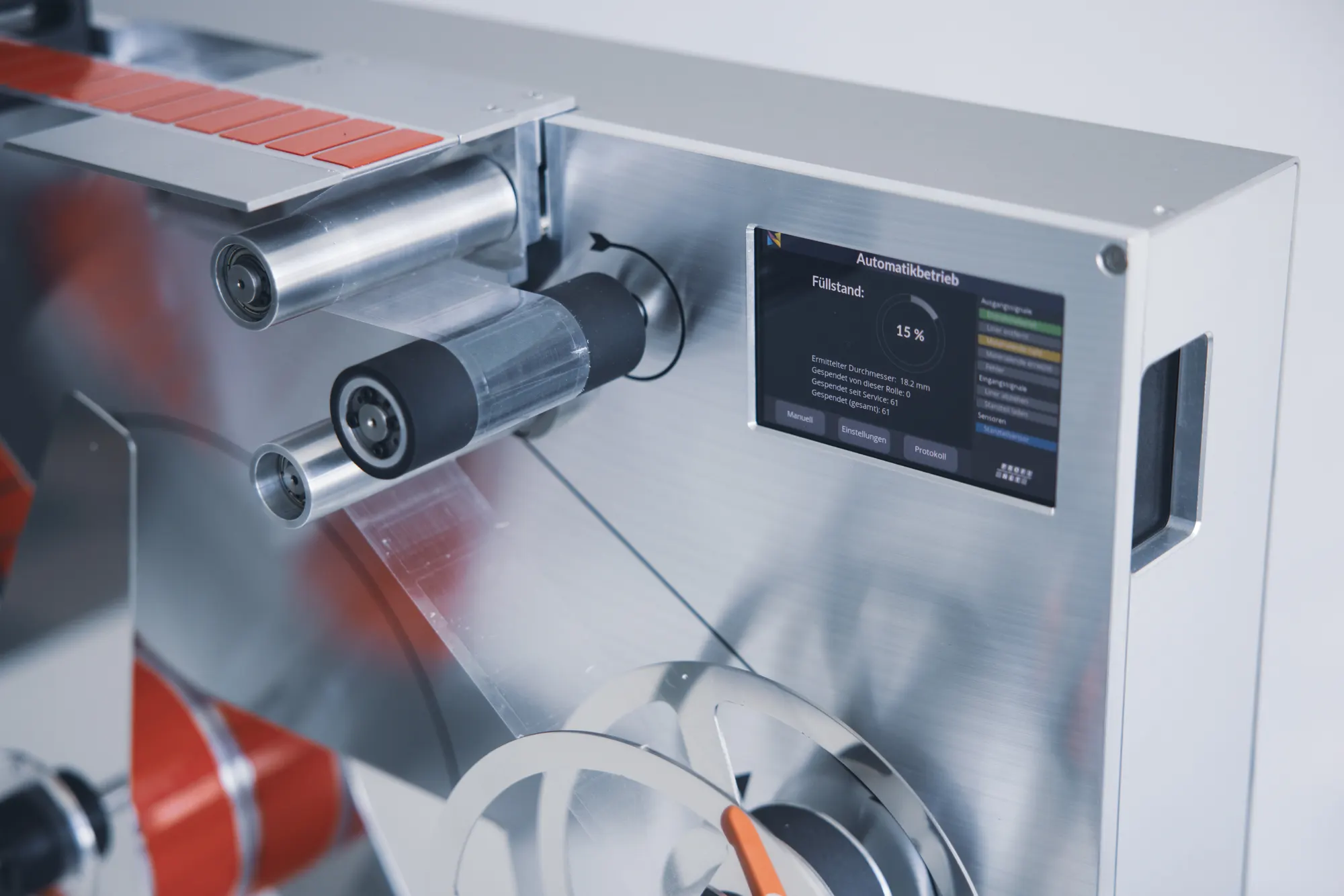
Precise remaining-material information and reliable die-cut pick-up ensure dependable operation. Automatic tape-break detection supports controlled process operation at all times.
- Automatic tape-break detection
- Precise die-cut position detection for reproducible robot programming
- Real-time consumption and process data via fieldbus
How Is High System Availability Achieved?
Redundant dispenser pairs keep the line running, and a four-unit tower variant is available, typically for two die-cut types with two dispensers each. The tower can form part of the robot cell's safety fencing, with parts removed on the inside and material reloaded by operators from the outside.
- Two-unit or four-unit tower configurations for redundant supply
- Tower can form part of the robot cell's safety fencing
- Operates without compressed air, in a fully enclosed housing
- Four brushless servo drives for reliable, low-heat continuous operation
How Fast Can Parts Be Dispensed?
Typical cycle time is around 1 second per die-cut, with adjustable liner removal (approx. 0.3 s) and next-part positioning (approx. 0.7 s).
Real application footage of the P&P-DCD material flow.
Which Materials Can Be Processed?
The system can be equipped with different die-cuts and adapted to your process, from varying diameters to demanding shapes and reflective surfaces, including double-sided adhesive pads, with automatic centering for reproducible gripping.
Adjustable die-cut diameter / liner width up to 100 mm
Explicitly supports double-sided adhesive pads, not just single-sided die-cuts
Material roll diameter up to 400 mm
Core diameter 3" (76.2 mm) or 6" (152.4 mm)
How Is the P&P-DCD Integrated Into the Line?
Fieldbus interface, pick position, material dimensions, and installation space are flexibly matched to your line. Settings can be loaded centrally via fieldbus, while the robot and gripper remain on the line side.
Technical Specifications
| Supply voltage | Var. A: 100–240 V AC, 2.6 A, 50/60 HzVar. B: 24 V DC, 8 A |
| Dimensions | 660 × 560 × 242 mm (W × H × D) |
| Weight | 29 kg |
| Cycle time | typically approx. 1 s |
| Liner removal | adjustable, typically 0.3 s |
| Positioning of next die-cut | adjustable, typically 0.7 s |
| Die-cut diameter / liner width | adjustable up to 100 mm |
| Max. material roll diameter | 400 mm |
| Core diameter of material rolls | 3" (76.2 mm) or 6" (152.4 mm) |
| User interface | 5-inch LCD, PCAP touch, glass surface |
| Fieldbus interface | PROFINET / EtherNet-IP |
| Operating temperature range | 10–50 °C |
P&P-DCD systems in production worldwide
Proven in Automated Production Lines
More than 140 P&P-DCD systems are deployed worldwide in automated production lines at OEMs and suppliers.
Questions About Integrating the P&P-DCD?
Most integration questions can be resolved quickly in a personal conversation.
Get in Touch